Figure 2. Buttons to control contents of text section
- Logfile: show result of checks (default)
- STEPfile: show clear text encoding of the exchange
structure, i.e., the STEP physical file that
was processed
- Schema: show the underlying EXPRESS specification
of the entity types etc.
- Other: lets you choose another file to display
(Note: see also
Load other logfile in next section)
As described further below,
'lv' will use the displayed
text as a vehicle for browsing through the geometry. Hence
the "STEPfile" mode is useful to perform analysis on
the file contents itself (not chosen by default so that
loading of huge STEP files can be avoided under low-
memory conditions).
The "Logfile" mode makes it easy to determine the
location of errors that are reported. This is also the
prime purpose of the "Other" mode: It is possible
to load the output of other STEP checking tools or
STEP translators and locate the errors reported therein.
The "Schema" mode can be used to find the definition
of the entity types that are the base of instances which
are interactively selected.
Additional features for browsing through the text
section are described at the end of this section,
because their usage context can be understood easier
after the other interaction basics have been explained.
The geometry display initially shows a view of the
geometry data contained in the file in the -z direction.
By default, the geometry is shown in tones of black/grey
on a white background.
Below the geometry display, the current status gets displayed.

Figure 3. Status display below the geometry display
The status display will show the following five key parameters:
- Task:
Displays the processing step that is currently
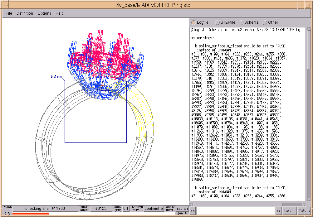
being performed by 'lv' (e.g. "checking shell #11933").
A number of computations and checks are preprogrammed
and will be performed one after another. A bar below the status display shows
the progress (percentage of completeness) of the task being displayed as
current. If the displayed task contains an instance name (e.g. "#11933"),
the display can be selected and the named instance will be
highlighted in the geometry display, to allow to track the process.
- Instance: Displays the instance that is currently being processed
within the current task (example: "#8125"). Again, the displayed instance
name can be selected to highlight it in the geometry display.
- Acc(uracy) (mm): Indicates the accuracy of the geometric model,
converted to a millimetre basis (e.g. "0.1").
The value shown is usually the one that
is given in a global_uncertainty_assigned_context as the
'distance_accuracy_value'.
However, in case an accuracy value was specified on the command line using
the -sa option, that value will be displayed.
In case the product contains several different accuracy values (for different
parts of the geometry contained), the display will show the accuracy range
(e.g. "0.01-0.1").
- Length unit: The length unit that is used in the product (e.g.
"centimetre"). This unit is supplied in a global_unit_assigned_context.
In case the product contains different length units for different parts of the
geometry contained, the display will contain the word "MIXED". This condition
should be treated with suspicion: Although it is perfectly legal in STEP to
use different length units in a single product (e.g., different units for
the different components of an assembly), it is a condition for which not all
STEP translators are well prepared.
Note: all distance values reported by 'lv' are always converted to a
millimetre basis, regardless of the original length unit in the product.
- Angle unit: The angular unit (plane_angle_unit) that is used in the
product (e.g.
"radian"). This unit is supplied in a global_unit_assigned_context.
In case the product contains different angular units for different parts of the
geometry contained, the display will contain the word "MIXED". This condition
should be treated with suspicion: Although it is perfectly legal in STEP to
use different angular units in a single product (e.g., different units for
the different components of an assembly), it is a condition for which not all
STEP translators are well prepared.
Note: all angle values reported by 'lv' are always converted to a
degree basis, regardless of the original plane_angle_unit in the product.
After all preprogrammed processing steps have been completed, the
progress indicator bar below the status display and the display for the
current instance will be removed, and
"idle" will be displayed as the current task.

Figure 4. Status display after processing has been completed
The display shows some "decorations":
- a square frame with a tag shows the scale of the model
(using a metric system). This frame can be switched off, as described in
the section on Menu functions.
- the orientation of the coordinate system is shown.
The coordinate system shows the XYZ-axis independent
of the scale. Only axes are drawn that are completely
inside the view (i.e., if the origin (0,0,0) is not
visible for the current view magnification, the
coordinate system is not visible). The coordinate system can
also be explicitely suppressed, as described in
the section on Menu functions.
The view's scale, rotation and placement can be manipulated
in a number of ways.
When holding down the Ctrl key, movements of the
mouse pointer in conjunction with one of the mouse
buttons have the following effect:
- Left button: view is rotated according to horizontal/
vertical mouse movements, around the Y and X axis,
respecively. When holding down the Shift key in addition,
the view rotates about the Z axis according to vertical
mouse movements.
- Middle button: Following the vertical movements of
the mouse, the view is zoomed out (upward movement)
or zoomed in (downward).
- Right button: Displayed object moves to follow the
mouse pointer.
If neither Ctrl key nor mouse buttons are pressed, 'lv'
will automatically highlight the topologic or geometric
instances that are below the mouse pointer. These are
drawn in red color, and a tag is displayed that identifies
the instance. The tag consists of a type code and the
actual instance name.
A list of the type codes used can be found at the
end of this section.
For the highlighted instance, the coordinates that
are under the mouse pointer are displayed.
Depending on the product, the following coordinate
values are displayed:
- At the bottom of the display, the 3D "world"
coordinates get displayed
- Should the product be an assembly, the local
coordinates (i.e., the coordinate space in which
the highlighted part of the assembly is defined)
get displayed directly above the world coordinates
- At the top of the display, the current location's
parameter space coordinates get displayed:
- for curves, the projection onto the curve
(syntax: "T (parameter)")
- for surfaces and faces, the projection onto the
(base) surface (syntax: "UV (para, para)")
Coordinate value display can, however, be turned off as described
in the section about Menu functions.
Furthermore, if the option Show
vectors is selected
(see following section),
'lv' draws a vector, using blue
color (= decoration color), that shows:
- for highlighted surfaces, the direction of the normal
under the pointer,
- for highlighted curves, the direction of the tangent
under the pointer,
- for highlighted topological entities, the tangent/
normal of the underlying curves/surfaces (Note:
possible re-orientations of these underlying elements
done by the topological entities are *not* taken into
account).
The tip of the vector is drawn in blue if the vector
points away from you, and in red if it points towards
you.
Note: This feature is also useful to determine the
exact location of any displayed coordinates, see above:
The base of the vector shows the spot which was
captured by the mouse pointer.
Whenever, due to the current perspective, several
instances overlap under the pointer's position, the
instance that is closest to the viewer gets highlighted.
This feature can be used to determine the relative
position of the instances. For example, to find out
which one of two overlapping faces is in front, one
can set the mouse pointer to an intersection of their
isoparametric lines (drawn grey) to see which is the
closest one.
Actions on highlighted instances
If an instance is highlighted (= drawn in red), clicking
the mouse buttons has the following effects:
- Left button:
- If the text section is in "Logfile", "STEPfile", or
"Other" mode, then all occurrencies of the
instance name within the text section are drawn
in reverse video.
The text gets scrolled, if necessary, to show the
first such occurrence (i.e. if no reverse video
portions are visible, the instance name does not
occur within the text).
If an occurrence of the instance name within the text
is immediately followed by '=', that position will
be displayed.
This feature can be used to find occurrencies of
the highlighted instance in a logfile, or to find
the definition of the instance in the STEP file.
- If the text section is in "Schema" mode, all
occurrencies of types the highlighted
instance posesses will be drawn in reverse video.
The text section gets scrolled, if necessary, to
show the instance's primary entity type definition.
- Middle button: If the highlighted instance is a
face_surface or a surface, the display switches
to "parametrics mode".
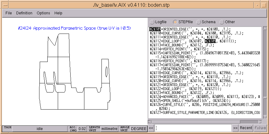
It then shows the 2-dimensional parametric space of
the instance. To be more precise, it is a polygon
approximation of the parametric space that was
constructed by 'lv'`s face trimming algorithm.
It contains polylines that represent approximations
of the bounds and the isoparametric lines.
When applying the highlight feature, the tags will
identify the names of the approximated bounds or
the key values of the isolines, respectively.
The following actions will not work:
- Mouse: Ctrl-Left Button: Rotation is not possible
- Marking (see below)

Figure 5. Sample shows geometry display in parametrics mode, and text section in "STEPfile" mode with a selected instance
Also, note that while it is possible to zoom the
display, the bounds are not "smooth to any resolution"
(as they are in normal, 3D mode). With sufficient
magnification, the bounds will become tangent
discontinuous.
The parametric space display contains, as a decoration,
the name of the face_surface or surface displayed.
In addition, if the surface's parameter space
extent in u and v is highly different, the display
is normalized to give a more square shape; in this
case, the true u:v ratio is also displayed.
Pressing the middle mouse button again will resume
the normal, 3D display.
Pressing the middle mouse button in 3D mode with other
than a face_surface or surface highlighted has no
effect.
- Right button: The view is zoomed and moved so that the
highlighted instance fills the display. Also, the
center of rotation (for Ctrl+Left button operation)
moves to the center of the highlighted instance.
Pressing the right button when no instance is
highlighted will reset the view to the initial
scale/position/center-of-rotation settings (only
the current angular orientation will be kept)
Marking occurs to items that the text section's cursor
is positioned onto.
The text section's cursor can be positioned in a variety
of ways, including
- clicking on an item,
- using the arrow keys.
In "Logfile", "STEPfile", and "Other" mode,
whenever the text section's cursor is placed on an
instance name, the corresponding topology and/or
geometry instances in the display are marked - that is,
they are drawn in green, and the instance is tagged.
Marking always occurs to the instance itself and all
dependent instances (e.g. mark a presentation_layer_assignment
-> all items in that layer are drawn in green).
Whenever an instance gets marked that is not visualized
by itself but takes part in the definition of some
visualized instance(s), the next available instance
that is visualized will be marked in the display.
The tag, however, will indicate the name and type of
the marked instance (Example: name of a cartesian_point
that is used as a control point of a b_spline_surface is
under the text cursor -> b_spline_surface gets marked
in the display.
Note: The tag, in this case, does *not* indicate the
cartesian_point's location)
The text section's cursor jumps to the position where
the instance name is followed by a '=', if any.
In this situation, switching the text section to "Schema"
mode will show you the definition of the instance's
type.
This feature can be used to easily identify problem
geometries ("Logfile"/"Other" mode), or to browse
through a STEP file ("STEPfile" mode).
In "Schema" mode, all occurrencies of the text string
under the text section's cursor are drawn in reverse
video. If this string is a valid entity, type or
function name, the text section scrolls to the
position where the item is defined. Furthermore, if the
string is an entity name, all instances of that type are
marked in the display. The tag will denote the entity
type that is marked. In this situation, when switching
to "STEPfile" mode, all occurrencies of that entity name
are drawn in reverse video (=all instances).
Use this feature to find instances of a specific type.
In the normal, 3D mode, it is
possible to suppress elements temporarily from the graphic representation.
Whenever geometry instances are marked (see above),
pressing the F1 key will suppress all unmarked instances.
The suppressed graphical elements will remain invisible until the
F2 key is pressed, which resumes the display of all elements.
Or, mark some other instances and press the F1 key once more:
this will again make everything disappear, except for the now marked instances.
This second part of the text section description now
explains the remaining possibilities to position the
text section's cursor.
Under the text section, you can see a text field which
has "<<" and ">>" buttons to its sides, and to the
right, two buttons labelled "Recent" and "Future".
If a string (like an instance name or an entity name)
is highlighted, the text section's cursor is usually
positioned on the occurrence of the string that provides
a definition.

Figure 6. Additional elements under the text section for searching and history management
When the text field is empty, you can use the "<<" and
">>" buttons to position the text cursor to the previous
("<<") or next (">>") occurrencies of the selected
string, with the text section getting scrolled if
required.
For example, in "STEPfile" mode, this is a convenient way
to find instances that reference the selected instance.
If you type a string into the text field, the "<<" and
">>" buttons will search for this string within the
text section in the given direction, and position
the text section's cursor accordingly. This can be used,
for example, as a means to find a specific type of
instance quickly.
Search always wraps around if the begin ("<<") or
end (">>") of the text section are reached.
Once you have selected a number of instance names, for
example, you might want to go back to one of the
instances you selected earlier. Clicking on the "Recent"
button will re-select the previous selection. As long
as you do not select another string manually, you can
also move forward to the newer selections again, using
the "Future" button. These two buttons are only
clickable if appropriate selections are buffered.
'lv' maintains two independent selection buffers: One
for "Logfile"/"STEPfile"/"Other" mode, and one for
the "Schema" mode.
For "Logfile", "STEPfile", or "Other" mode:
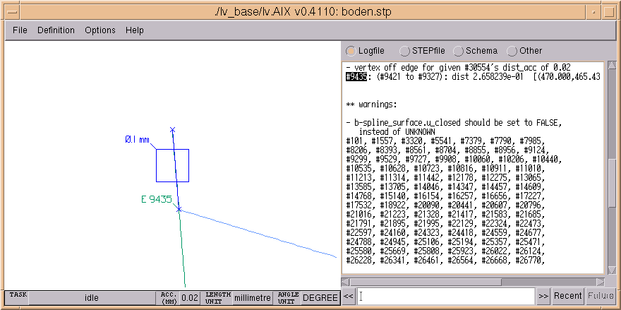
If the line in the text that contains the text section's
cursor contains one or two 3D coordinates (syntax should
be "('val','val','val')" ) then these coordinates are
marked in the display by a cross ("x"). If there are
two such coordinate values within the same line, they
are connected in the display.
This feature is useful to find a graphical representation
of the errors reported (e.g., vertex off edge).
(Note: It can also be used to see locations of instances
like cartesian_points used as control points of a
b-spline, provided that
- the product is defined in a mm (millimetre) context,
and
- the point's coordinates are printed on a single line
of text, without a line wrap.
Alternatively, the
"Describe base geometry" option can be used to locate
control points.)

Figure 7. Example shows a marked and tagged instance. Note the indication of coordinates ("x"es)
All the colors mentioned above (background, marks, etc)
are the default colors. In case a STEP file defines its
own colors, 'lv' might automatically use different
colors (for background, marks, etc) in order to guarantee
that everything is visible (i.e., avoid drawing white
geometry on white background etc.).
If a STEP file contains such styling information, then
geometry instances for which no styling is defined would
have to be invisible according to part 46. Instead, 'lv'
will make them blink (default, see
Menu functions and options).
It is also possible to configure the default colors that
'lv' uses. This can be done using the -c
option (see
Command line options)
or by storing a default
configuration file in 'lv'`s base directory.
Type codes used in tagging geometry
As a reference, here is a list of the type codes 'lv' uses when
tagging geometry in the display, together with
their meaning:
Help Index
© lv: visit us on http://www.wundertools.de/
This page last updated: 1998/10/02


